December 17th, 2010 - ShapeStart Project Day
ShapeStart project days occur about once a quarter. It is a day where the developers and engineers at ShapeStart can work on any project they want and can work with whomever they want. Check out ShapeStart’s project day page for more information. http://www.shapestart.com/project_day.html
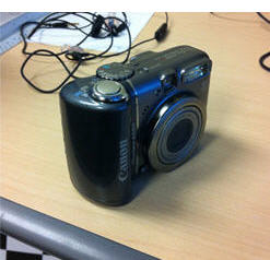 I decided to build a 3D foot scanner using the canon powershot A590 and the matlab calibration toolkit (I could have used any point and shoot camera, as long as the autofocus can be disabled. There is also a way to make this work even with autofocus enabled, although it is much less straight forward and since I had only day to try and make this work. I decided to implement a non-autofocus version for now)
The Idea
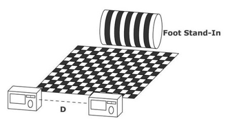
I used the point and shoot camera as a stereo rig seperated by a distance D. I’d grab the position of cameras from the checker board, and use a pattern printed on a foot “stand-in”(which was a peanut butter jar wrapped with a printed pattern) to find correspondence. In a real foot scanner, we’d have to use a sock with a similar printed pattern.
First I should explain the principal that I used for this scanner. I actually built upon the idea I created at a previous project day. The previous project day I built a foot scanner that used two fire-i board cameras mounted to a steel plate.
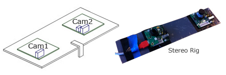
The foot scanner uses the principal of stereo vision. On the first project day I actually just used the matlab cailbration toolkit, stereo calibration procedure to calibrate this stereo rig. Then I used the image rectification option to rectifiy two images of the “foot” pattern. Once the images were rectified the pixels along the translation axis are all aligned. If the lens calibration is perfect, any line drawn parallel to the axis of translation should intersect the same points in the two images:
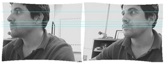
Note: If you’re good at it you should be able to cross your eyes and see me in 3D, if you dont know what I mean check this out:
http://www.3dphoto.net/text/viewing/technique.html.
I then used canny edge detection to find the edges in the “foot” pattern. In the original setup the center bar is double the width of the other bars. This is so I could find the proper correspondence between cameras(figure out which line was which in each picture even though the bars were not coded). So once I knew which lines were the same in each picture and the images were rectified it was a simple matter of triangulation. Please take a minute and check out my article on Stereo Vision.
With this new, more generalised setup, the distance D was unknown. However, I was able to find the 3D positions of both cameras relative to a checker board using the Matlab calibration toolkit. Then using the two transform matrices I was able to put both cameras in the same “world coordinate system”. Once the cameras were in the same coordinate system, I had to find the corresponding pixels in each image, then triangulate the distance to the XYZ point in space where the correspondence match occurs. One way to think about this is to imagine a ray drawn from the theoretical camera center through the pixel on the image sensor, (ignoring lens distortion) this ray will also intersect the correspondence point.
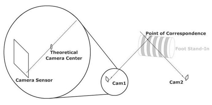
I say theoretical camera center, because in reality lens distortion makes this more of a region then the theoretical pin-hole of a camera. So to find the 3D position of our point of correspondence, we just need to construct two rays, one from each camera, and find where they intersect. In theory this is simple, but in reality, lens distortion makes this quite complicated. I was on a time constraint (1 day) for project day, so I decided to just use the matlab camera calibration toolkit’s undistort function. Once the image is undistorted, it is as simple as constructing a ray from pixel through camera center.
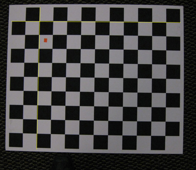
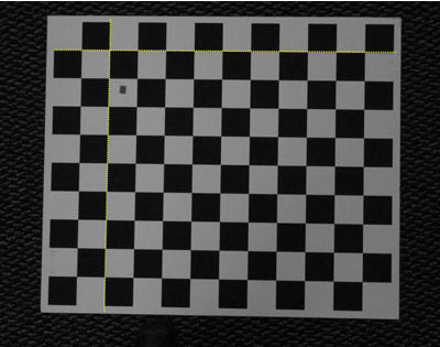
Below, you can see an example of a distorted image vs an undistorted image. This is the same picture of the checker pattern. The first is straight out of the camera, you’ll notice the checker board is actually warped(deviates from the yellow line which I drew in photoshop). Of course, in reality the checker board is not warped, so the warping you are seeing is caused by the lens of the camera. The undistort function applies the lens calibration parameters to the image to remove this lens distortion. You can see in the undistorted version of this same image below, the checker board is indeed straight and stays in contact with the yellow line I added in photoshop.
Now to construct the rays. First I had to identify the points of correspondence, last project day I built some code that used canny edge detection and a double thick center bar to determine points of intersection from both cameras. My original thought was I could grab that code and implement it here, however after about 2 hours of trying to get that to work, I gave up and manually clicked points of correspondence just to keep moving. Here are the corresponding pixels I used. l_x represents left camera x pixel, so the first number in l_x should be the same point as the first number in r_x, etc:
l_x=[726 729 727 725 769 770 770 769 812 813 814 812];
l_y=[188 149 108 70 189 152 110 71 188 153 111 72];
r_x=[575 574 574 576 620 618 618 618 663 660 661 663];
r_y=[151 118 80 41 154 119 79 41 155 119 81 41];
To construct the rays I just created two points, one at the camera center, translated to “world coordinates” (so both rays would be in the same coordinate space), and the second point is the pixel on the camera sensor where the correspondence occurs. Here is the code for this:
%construct the first ray
ray1_pt1=Rc_l^-1*([0;0;0]-Tc_l);
ray1_pt2=Rc_l^-1*(KK^-1*[l_x;l_y;1]-Tc_l);
Definitions for KK, Tc, Rc, etc are on this page:
http://www.vision.caltech.edu/bouguetj/calib_doc/htmls/parameters.htmlThen to find the intersection of the two rays (actually the point where they are the closest, since they will probably never perfectly intersect) I found the normal distance between the rays at every possible point along the ray, for each ray, and stored the location where it was the smallest. I call this brute force because its insanely inefficient. I didn’t have time to speed it up, I could probably do something with the cross product, or maybe figure out a way to locate an area of likely intersection and use the brute force over a small area. Anyway, the brute force method worked.
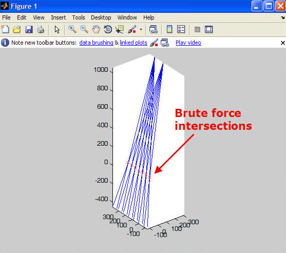
From this second view you can see it is 3D scan data, in the shape of the stand-in.
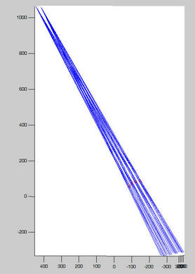
There are, however, inaccuracies because the cameras are not epipolar and that is one of the assumptions I made in this setup. Two solutions to this are to use a “3D curve” reconstruction technique, rather than a point to point reconstruction or use a pattern where the epipolar constraint is not necessary, such as a checker pattern or stripes with ticks marks parallel to the axis of translation.
Here is my Matlab code:
foot_v2.m
stereo_match.m

 Entrepreneur